In this C# electronics tutorial, you will write a .NET application to display text onto a 16x2 (or 20x4) LCD character display connected to a Raspberry Pi.
Wiring the Hardware
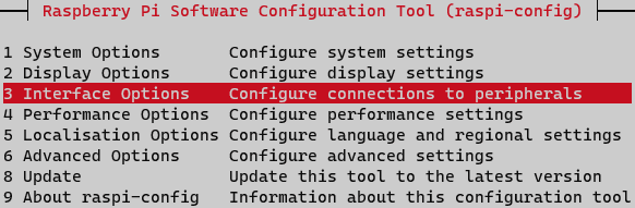
To communicate with the LCD display, our code will rely on an I2C bus. Be sure the I2C interface is enabled on your Raspberry Pi. I have already configured my Raspberry Pi to allow connections over SSH, so I will simply tunnel in, run sudo raspi-config, and enable the I2C module from the Interface Options menu.
Using the I2C interface allows us to connect our LCD display using only two of the Raspberry Pi's GPIO pins - namely the I2C clock and data lines. Connect any 5V power pin from the Raspberry Pi to the positive rail on your breadboard and connect a Ground pin to the negative rail.
If your LCD character display does not have an integrated I2C module, you can create your own using a MCP23008 I/O expander. It is important to consult the datasheet for any integrated circuit chips you are not familiar with. The MCP23008 can be powered by either 3.3V or 5V.
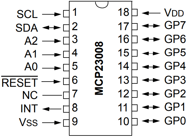
Connect the SDA and SCL pins of the Raspberry Pi to the SDA and SCL pins of the MCP23008 chip. Your Raspberry Pi connections are already complete (4 pins!).

Wire VDD of MCP23008 to the positive rail of the breadboard, and wire VSS to the ground rail. According to the datasheet, the RESET pin must be pulled high in order to active the device, so connect it to the positive rail.
I2C allows you to communicate with multiple devices on a single bus. All connected I2C devices must have a unique address. We can configure the address for our connected device by setting the value for the three address pins A0, A1, and A2. According to the datasheet, addressing for the MCP23008 I/O expander has four fixed bits (0b0100) followed by the values of the three address pins. In other words, there is an offset of 0X20. Pulling all the address pins low, for example, will result in a slave address of 0X20.
Now, wire the LCD display pins to the I/O pins on the MCP23008 chip. Take note of which pins you use, as we will configure the MCP23008 as a serial driver in our C# code later. In my circuit, I connected the LCD's Register Select (RS), Read/Write (RW) and Enable (E) pins to GP4, GP5, and GP6 respectively. We will use 4-bit mode on our LCD, so connect D4, D5, D6, and D7 to GP0, GP1, GP2, and GP3 of the MCP23008. Now you are finished wiring the MCP23008 chip.
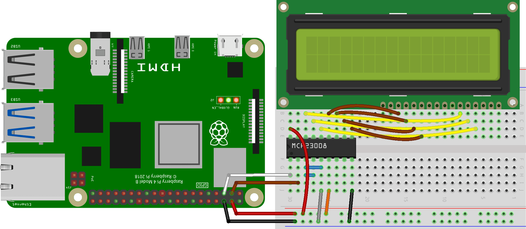
There are only a few LCD pins remaining to configure, and then we will get to the code. First, provide power to the board and enable the backlight. Pin 1 on my LCD display is labeled VSS. Connect this to the negative (ground) rail on the breadboard. Connect pin 2 of the character display (labeled VDD on mine) to the positive (5V) rail of the breadboard. Pin 15 is the anode (A) for the backlight power supply. Connect pin 15 to the positive rail. Then, connect Pin 16, the cathode (K), to the ground rail.
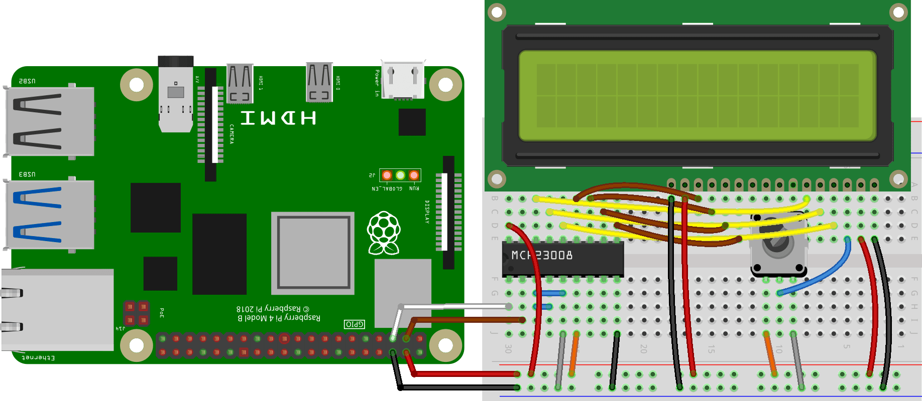
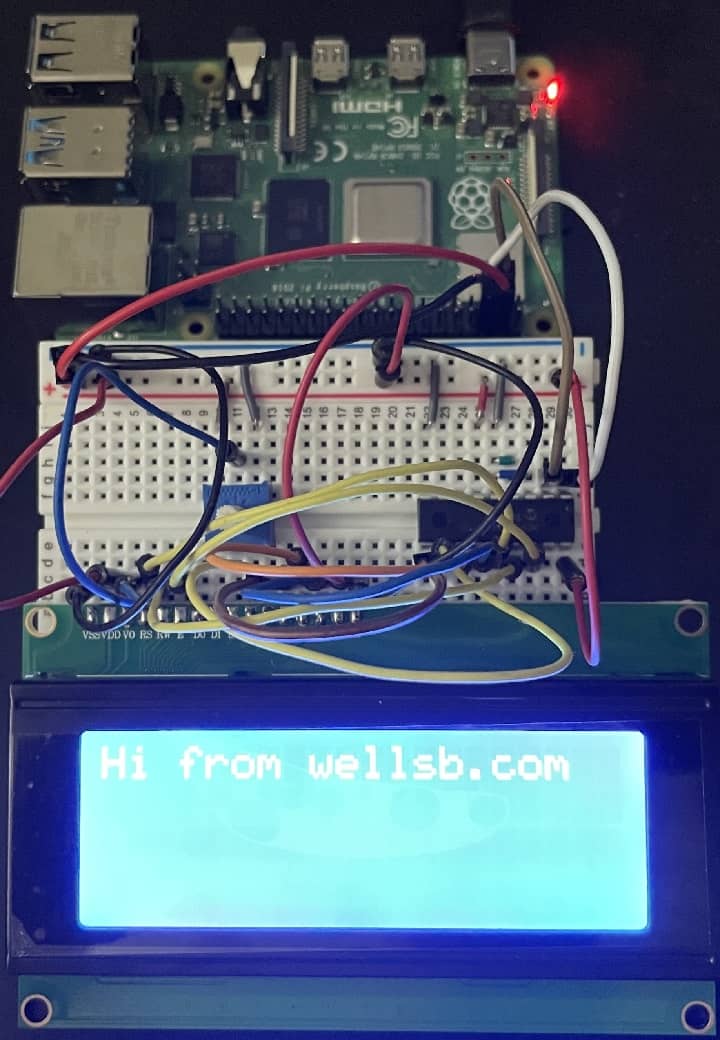
Finally, pin 3 (V0) controls the contrast for the display. It should be supplied a voltage somewhere between 0V and 5V. The easiest way to adjust the contrast is to use a potentiometer. Your final electronics circuit should look like the following.
Writing the Code
Create a new C# Console application. I will call mine RPiLcd. For this project, you will need to install the Iot.Device.Bindings Nuget package.
Install-Package Iot.Device.Bindings
Configure an I2C device with address of 0x20 as you configured before. Also, add a driver for the MCP23008 chip using the same I2C device,
using I2cDevice i2cDevice = I2cDevice.Create(new I2cConnectionSettings(1,0x20));
using Mcp23008 serialDriver = new Mcp23008(i2cDevice);
Next, create a new LCD device using the serial driver you just created. The pin numbers should correspond to the GPIO pin names of the MCP23008 that each corresponding LCD pin is connected to. If you are using a 20x4 LCD display, change Lcd1602 to Lcd2004.
using var lcd = new Lcd1602(dataPins: new int[] { 0, 1, 2, 3 },
                        registerSelectPin: 4,
                        readWritePin: 5,
                        enablePin: 6,
                        controller: new GpioController(PinNumberingScheme.Logical, serialDriver));
Now, let's write something to the screen! It is good practice to clear the LCD to remove any residual artifacts. The SetCursorPosition() method allows you to move the cursor to different columns and different rows.
lcd.Clear();
lcd.SetCursorPosition(0, 0);
lcd.Write($"Hi from wellsb.com");
Your final project code should look like the following.
using Iot.Device.CharacterLcd;
using Iot.Device.Mcp23xxx;
using System.Device.Gpio;
using System.Device.I2c;


using I2cDevice i2cDevice = I2cDevice.Create(new I2cConnectionSettings(1,0x20));
using Mcp23008 serialDriver = new Mcp23008(i2cDevice);
using var lcd = new Lcd1602(dataPins: new int[] { 0, 1, 2, 3 },
                        registerSelectPin: 4,
                        readWritePin: 5,
                        enablePin: 6,
                        controller: new GpioController(PinNumberingScheme.Logical, serialDriver));

lcd.Clear();
lcd.SetCursorPosition(0, 0);
lcd.Write($"Hi from wellsb.com");
Though you may have configured your publish options to produce a single file, the extra library file must be pushed to your Raspberry Pi separately. You will find it in the same target location folder you defined in your publish profile settings (e.g. your project's bin\Release\net5.0\publish\ directory). In a terminal window, change directory to the location above and push the files to your Raspberry Pi.
scp RPiLcd pi@192.168.1.10:/home/pi/RPiLcd/
scp libSystem.IO.Ports.Native.so pi@192.168.1.10:/home/pi/RPiLcd/
Tunnel into your Raspberry Pi and launch the program.
./RPiLcd/RPiLcd
The Bottom Line
In this tutorial, you wrote a C# application to interface with the GPIO pins on a Raspberry Pi and drive an LCD character display. This was all made easy using the GPIO libraries made available in .NET 5. You also learned a technique for conserving input/output pins using an I/O expander like the MCP23008. In this case, you were able to use the serial capabilities of the chip to enable communication with an LCD displaying using an I2C interface.
Now that you have mastered the basics of using an LCD display, why not take advantage of the other capabilities of your Raspberry Pi by fetching data from a web API or polling from a temperature sensor. If this tutorial helped you create a neat IoT project, let me know in the comments!
Don't stop learning!
There is so much to discover about C#. That's why I am making my favorite tips and tricks available for free. Enter your email address below to become a better .NET developer.
Did you know?
Our beautiful, multi-column C# reference guides contain more than 150 tips and examples to make it even easier to write better code.
Get your cheat sheets